Today I am going to discuss about two features of Eclipse GMF that are not well covered by the documentation and that are difficult to locate in forums. For this article I used the Eclipse Modeling Tools Mars 2 Package. After installing the package you must go to Help -> Install Modeling Components and select and install the Graphical Modeling Framework Tooling.
The first feature is to have text areas that can span multiple lines of text.
The second feature is to be able to print my model (as I may want to have it is xps or pdf format). By default GMF allows only for printing your models in png (picture) format.
I will take you step by step to these features definition using a simple example. Assume you have a newspaper and you want to publish articles. The page of the newspaper has one or more articles. Articles have a title, a teaser and text.
1. Create the project and the metamodel
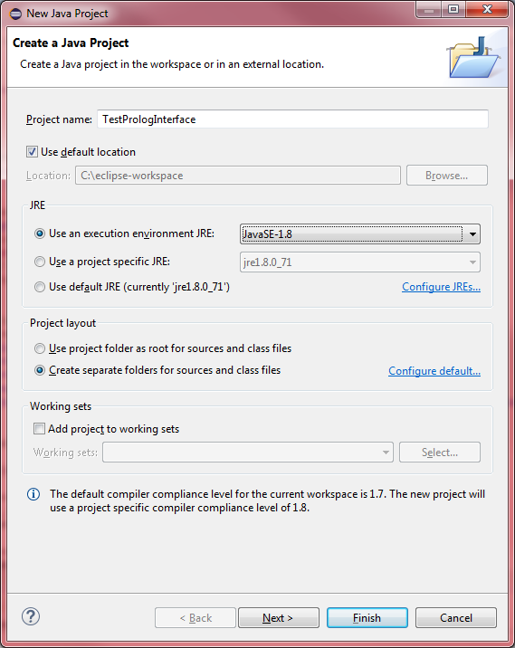
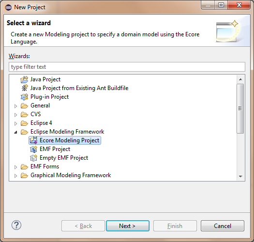
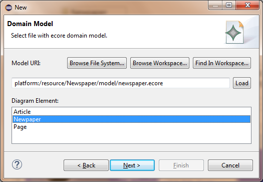
You first need to create a new Modeling project. File-> New-> Project..->Ecore Modeling Project (see the next figure).
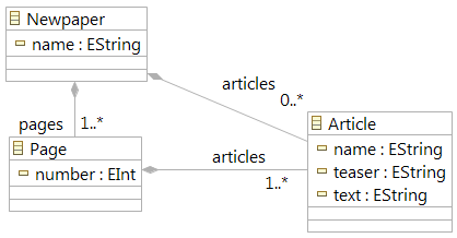
Now define the model as a collection of pages, and the pages are collections of articles. To do that right click on the newspaper.ecore file and click on “Initialize ecore_diagram diagram file”. Use the aggregation (or composition if you use the aird file) relationship from the toolbox and click and drag from the Newspaper EClass to the Page EClass and for Page to Article. Define the relationships and properties shown in the following diagram.
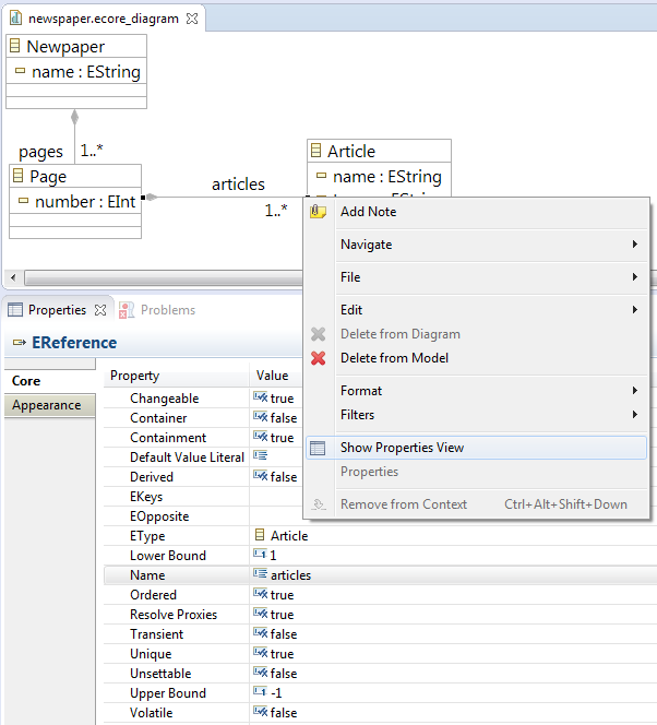
It is interesting to take a look at the properties of the aggregation. Right click on the line of the articles relationship and select the properties view (see figure below). To indicate that the articles can be from one to many you assign to the property “Lower Bound” the value 1 and to the “Upper Bound” the value -1.
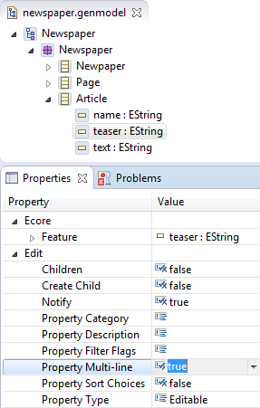
Now assume that you want the teaser and text properties of the Article to be able to have multiple lines of text (the first deature we discuss in this article). In order to do that you need first to open the genmodel file. Then you will select the teaser attribute and you set its “Property Multi-line” to the value true. By default it is false, so make sure to do that.
Finally select the top level node in the genmodel diagram and check its properties. Set the Compliance Level to 6.0 (if you do not do this then when building the gmfgen file you will get an error):

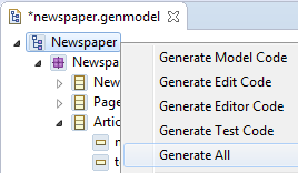
Now you are ready to initialize the code for editing the model’s elements. Right click on the Newspaper element of the genmodel and select “Generate All”. This will create the ecore Model Code in this project and generate the Edit Code project that you need.
2. Generating the Graphical Model
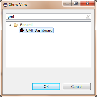
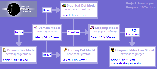
Now you are ready to start working with GMF. Open the GMF Dashboard. Select Window->Show View->Other and type GMF and immediately you will see the GMF Dashboard appear. Select it and you will see it in your eclipse window.
The first task is to select the ecore (Domain Model) and genmodel (Domain Gen Model) files:
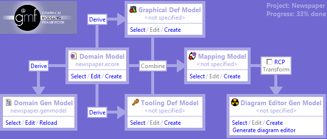
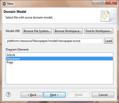
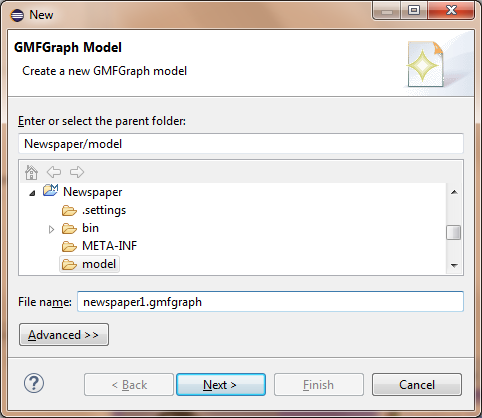
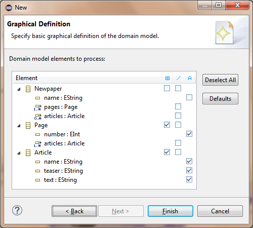
Next you derive the gmfgraph model by clicking Derive from the Domain Model towards the Graphical Def Model. I named it newspaper1.gmfgraph (see first figure below, in your machine you can give it the name newspaper.gmfgraph, I cannot because I already have one graph file). Then I selected the newspaper element in the Next step of the dialog (see second figure below), and in the final step of the dialog (see third figure) I selected that I want graphical representations for the Page (with the number attribute) and Article (with all its attributes, i.e., name, teaser and text).
Now if everything is OK you can see the following newspaper1.gmfgraph file on eclipse:
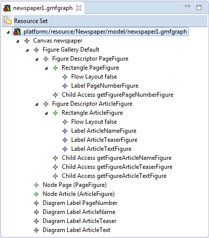
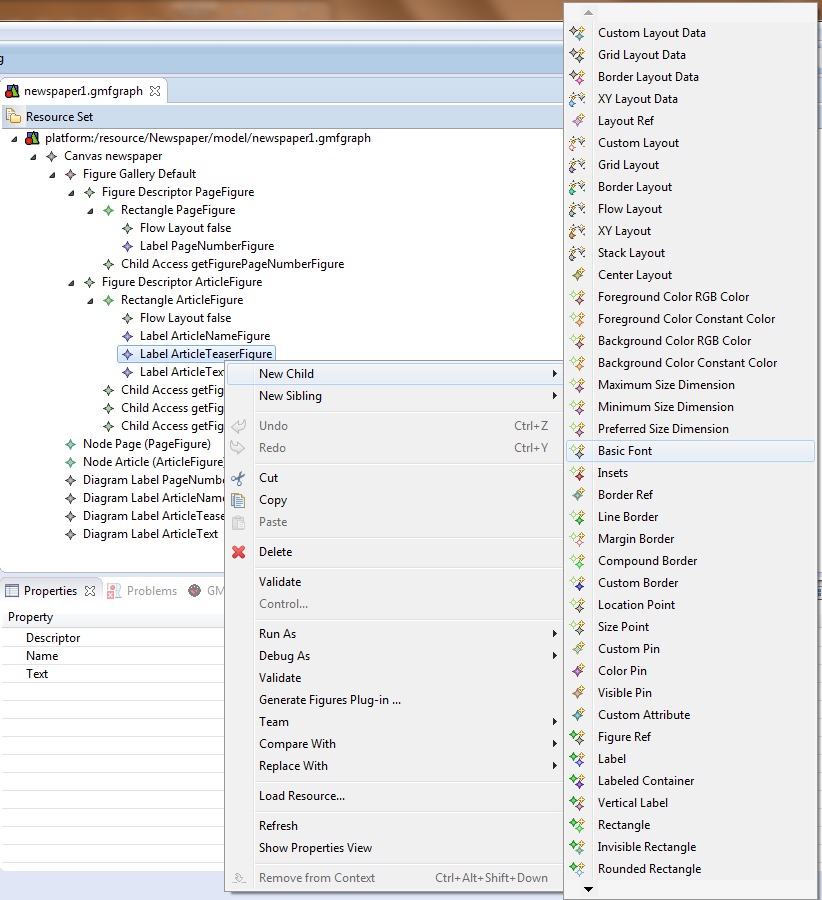
All elements are in the Canvas. The Canvas has a Figure Gallery (we will see it in detail later), the Node elements that refer to the objects that will be displayed and the Diagram Label elements that refer to the text boxes that will display attributes (bottom part of the figure). Now, in the Figure Gallery we have two main Figure Descriptors, one for the Page (PageFigure) and one for the Article (ArticleFigure). Each of these has a Rectangle with the default Flow Layout and as many Child Access elements as its text boxes (attributes). Note that this is not enough, there are also the relevant Labels defined in the Rectangle. The Diagram Label elements refer to the Child Access elements and the latter refer to the Label elements. In the Label element you can add children like Insets (to space the text from the limits of the rectangle) and a Basic Font to define text size and style – regular, bold or italics:
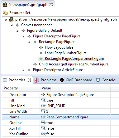
Now we need to define a new Rectangle in Page where we will be inserting Article objects. Right click on the Rectangle PageFigure and select New Child -> Rectangle:

Name the Rectangle element PageCompartmentFigure. See its properties:
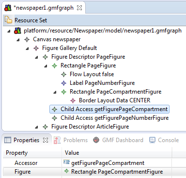
Now you need to add a Border Layout Data child to the PageCompartmentFigure and add to the Rectangle PageFigure a Child Access element with properties:
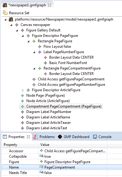
Now go to Canvas -> New Child -> Compartment, name it PageCompartment with the following properties:
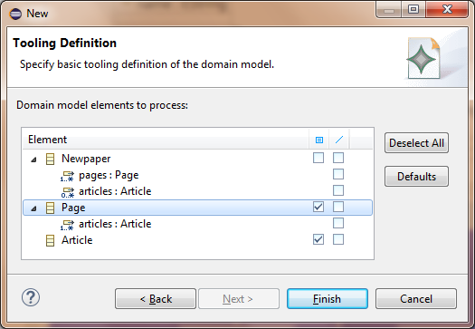
Save it and for now you are finished with the gmfgraph file. The next step is to go to the GMF Dashboard and Derive the gmftool model. First you select its name, then you select the newspaper element and finally, the two objects that you are going to be using to draw the model, i.e. the Page and the Article. See these three steps of the wizard:

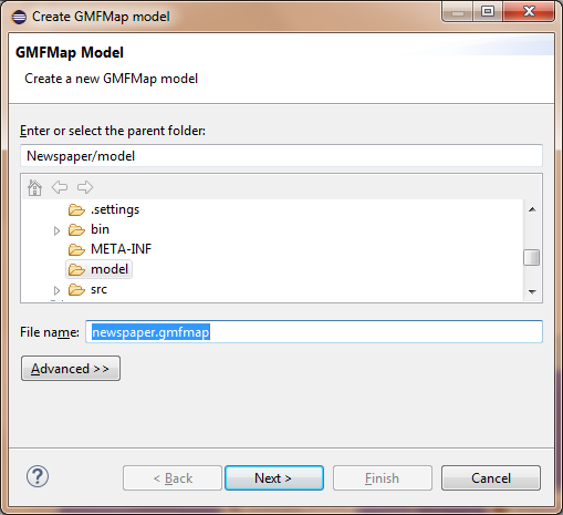
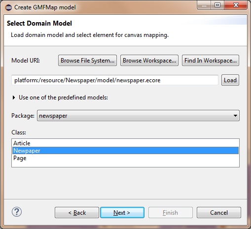
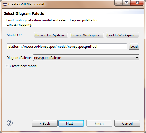
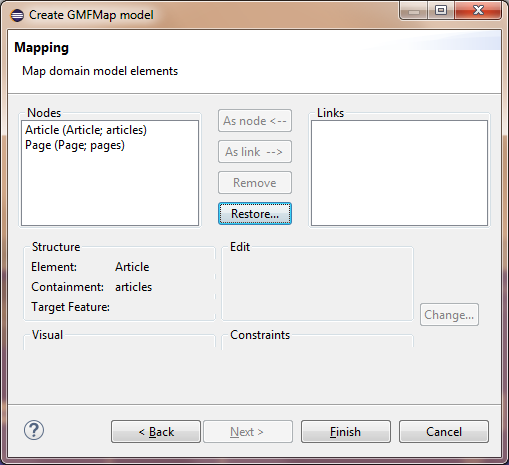
Now you are ready to Combine all these models (using again the GMF Dashboard) to get the gmfmap model. Follow again the steps of the wizard. Take care to remove Article from the Links compartment in the fifth step. It must look as in the fifth figure below:

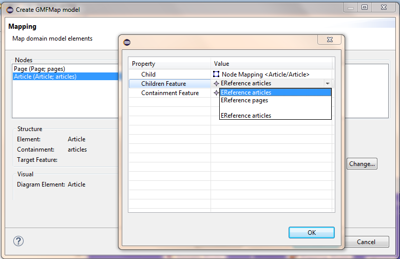
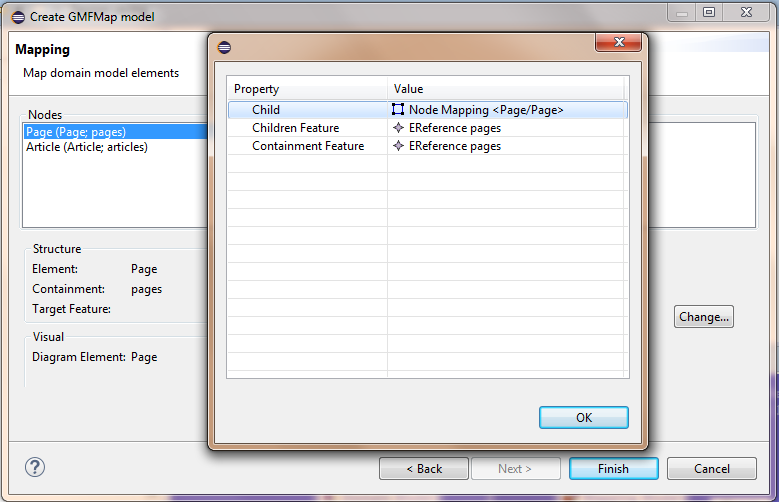
Then you have to take care of the Nodes Page and Article because they need a final touch. Select Article and then click the button Change. Add the first EReference articles to the Children Feature:
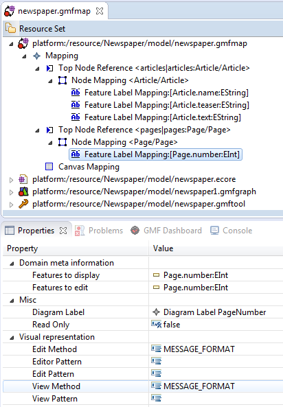
Now you have to edit the newspaper.gmfmap file. It is shown below. See that it contains the ecore, gmfgraph and gmftool models. We are going to focus on the gmfmap part. The Mapping has two elements of type Top Node Reference (one for articles and one for nodes) and a Canvas Mapping. Verify that the
Each Top Node Reference has a Node Mapping. The Node Mapping of Article has a Feature Label Mapping whose properties are displayed in the figure below:

Now you have to add the Feature Label Mapping that are missing with similar properties. Note that the one for Page (number) is not of type EString but of type EInt. I have its properties shown below:
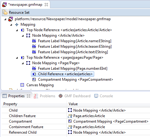
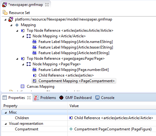
The final part in mapping is to add the compartment of the page.Right click to Node Mapping <Page/Page> -> New Child -> Child Reference and then again right click to Node Mapping <Page/Page> -> New Child -> Compartment Mapping. You do not have to type anything in their properties, just select the right items. See both their properties in the figures below:
Now save it, if all has gone well you are ready to press transform from the gmfmap model to the gmfgen model in GMF Dashboard. You finished the process:
Insert Printing Capability
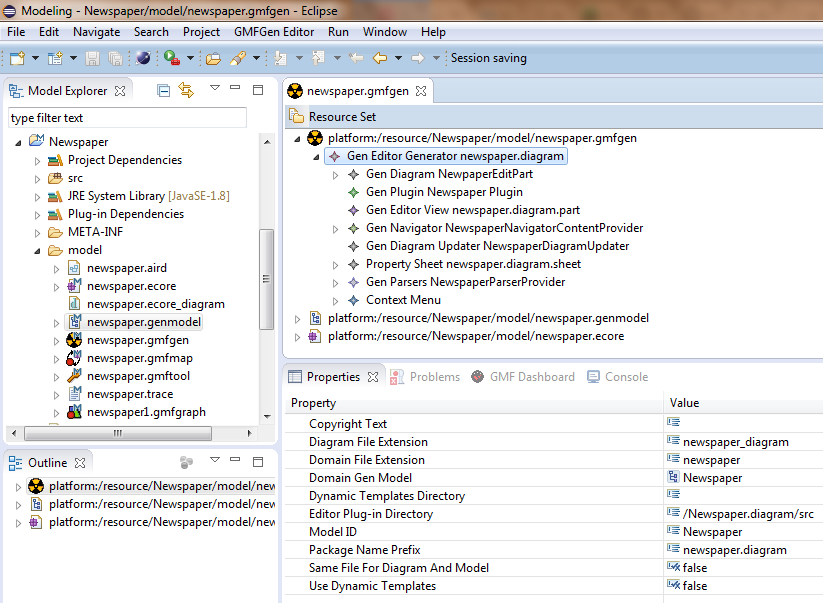
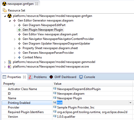
Double click the newspaper.gmfgen file to open it. Now you click its Gen Editor Generator top element. Its properties Diagram File Extention and Domain File Extention show the extentions of the files related to newspaper. The models will have the extention .mewspaper and the graphical models .newspaper_diagram. See also all the files in the models folder of our projet on the left:
Now select the Gen Plugin Newspaper Plugin element and set its property Printing Enabled to true:
Now your models will have the printing capability! Now save and right click on the newspaper.gmfgen file and select to generate the diagram code:

Add Text Multi-line capability
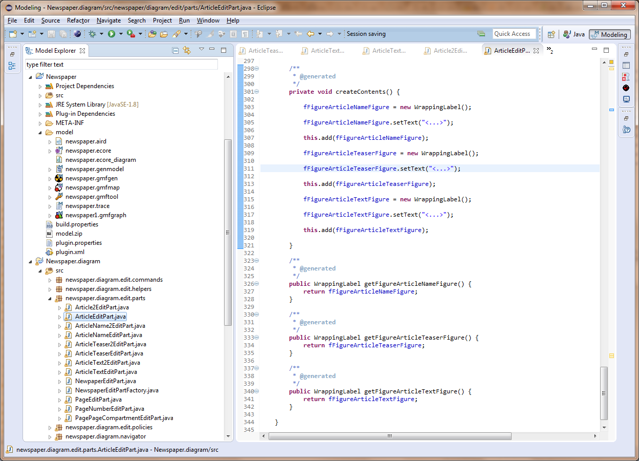
Normally the Newspaper.diagram project has been created successfully and you can see it in the following figure. It is ready to work with it. However, we want the teaser and the text elements of the articles to be able to span multiple lines of text. To achieve that you need to edit a number (six actually) java files in package newspaper.diagram.edit.parts. The first two files that you need to edit are the ArticleEditPart.java and Article2EditPart.java. You need to find their createContents() method. Initially it is like in the figure:
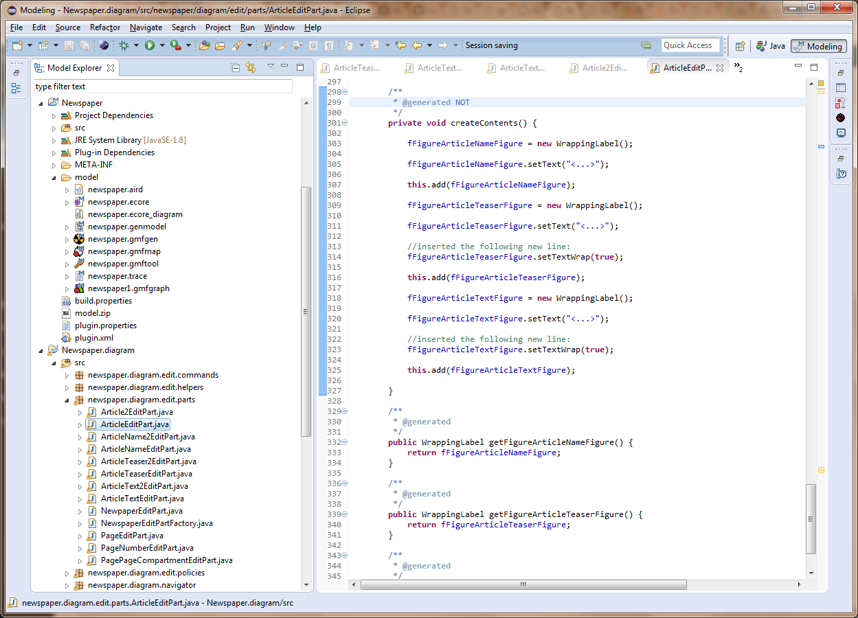
You need to locate the lines where the fFigureArticleTeaserFigure.setText(“<…>”) method is called and add the code:
fFigureArticleTeaserFigure.setTextWrap(true);
Do the same for the fFigureArticleTextFigure. Do not forget to set the method to not be automatically generated from now on (generated NOT). You must do that because if for any reason – e.g. you want to change the fonts of the labels – you re-generate the diagram code you will lose your changes. See the final outcome in the following figure:
You have to repeat the above process for file Article2EditPart.java.
Now you get the ArticleTeaserEditPart.java, ArticleTeaser2EditPart.java, ArticleTextEditPart.java, ArticleText2EditPart.java, and make another change. Take for example the first of them, i.e., ArticleTeaserEditPart.java, and locate its getManager() method:
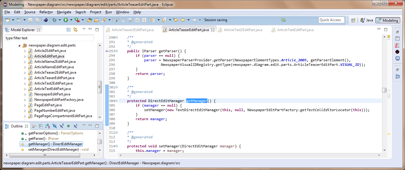
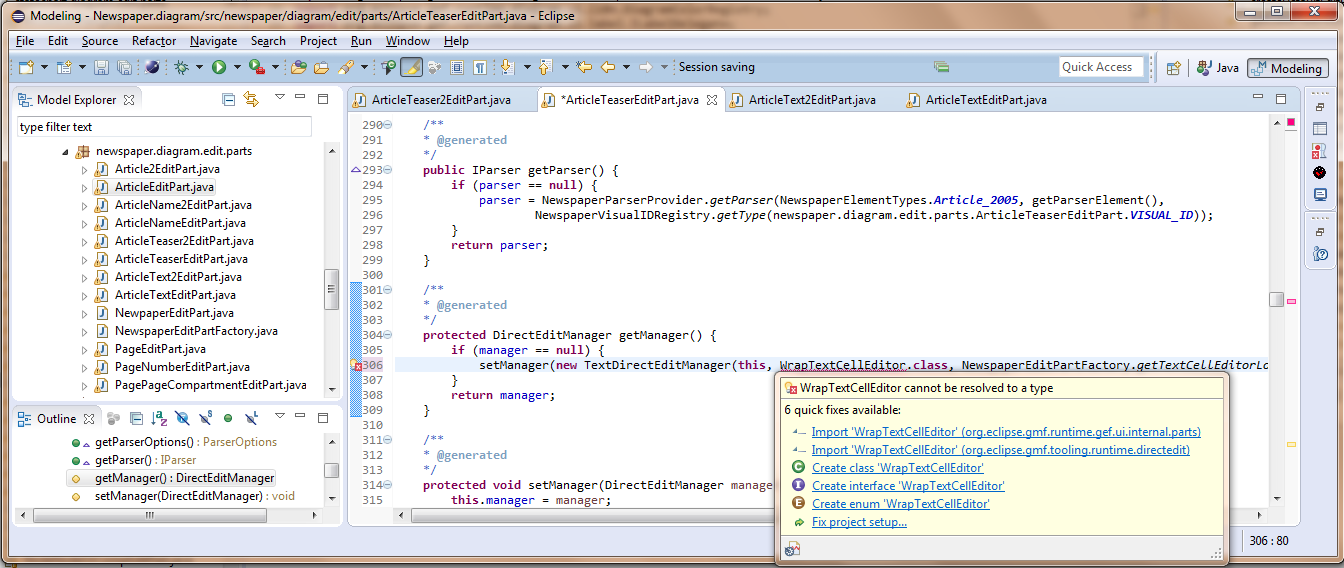
Now you have to locate the line with code:
setManager(new TextDirectEditManager(this, null, NewspaperEditPartFactory.getTextCellEditorLocator(this)));
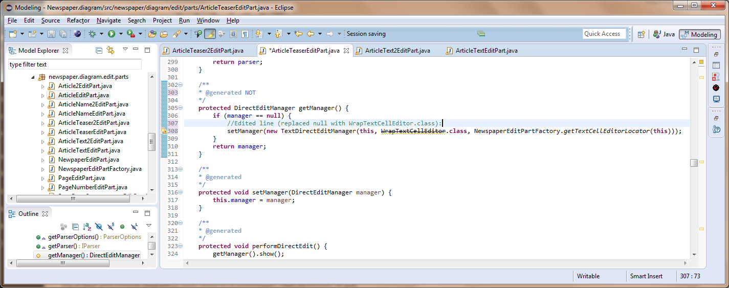
and replace null with WrapTextCellEditor.class. This classhas not been imported yet, so hover your mouse over it and select to import org.eclipse.gmf.runtime.diagram.ui.tools.TextDirectEditManager:
Then remember to add generated NOT and save it:
Do not worry about the deprecated warning, it is just a warning 🙂
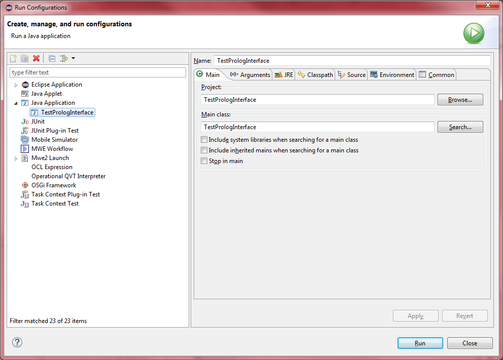
Now you have to do the same for the other three files. After that you are ready to test your model! To do that right click on your Newspaper.diagram project and select Run as -> Eclipse Application.
Create my first newspaper
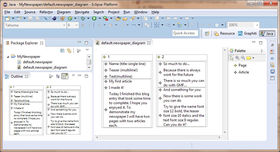
Create a new project and name it MyNewspaper. Then right click on the project and select New -> Example -> Newspaper Diagram
Let it have the default name and add pages and then articles. To add an element click on it at the palette on the right hand side of the following figure. Then if it is a Page click anywhere in the canvas to insert a page. If it is an Article click inside a page to insert it there. Then add your text:
Now do you want to print your model? Just right click on the canvas and select File -> Print:
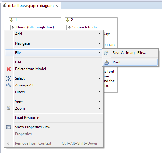
Enjoy!